Lubricated pumps “LE” Series
LE 30 / LE 45
Technical data
|
Code |
Model |
Air Flow (m3 / h) |
Motor Power (kw) |
Speed (RMP-1) |
Vacuum (mbar) |
Noise Level [dB(A)] |
Fil Oil (L) |
Weight (kg) |
Inch Suction Port (G”) |
|||||||
|---|---|---|---|---|---|---|---|---|---|---|---|---|---|---|---|---|
|
Three-phase |
Single-phase |
Three-phase |
Single-phase |
|||||||||||||
|
50Hz |
60Hz |
50Hz |
60Hz |
50Hz |
60Hz |
50Hz |
60Hz |
50Hz |
60Hz |
|||||||
|
300104 |
LE 30 |
30 |
36 |
0.9 |
1.1 |
0.9 |
1.1 |
1400 |
1680 |
1400 |
1680 |
0.5 |
67 |
1 |
36 |
1-1/4 |
|
300105 |
LE 45 |
45 |
54 |
1.5 |
1.8 |
1.5 |
1.8 |
1420 |
1710 |
1420 |
1710 |
0.5 |
67 |
1 |
46 |
1-1/4 |
Data sheet
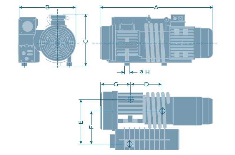
Dimensions
|
Model |
A |
B |
C |
D |
E |
F |
G |
H |
|---|---|---|---|---|---|---|---|---|
|
LE 30 |
600 |
280 |
280 |
308,5 |
230 |
159 |
132 |
30 |
|
LE 45 |
640 |
290 |
280 |
325 |
230 |
159 |
153 |
30 |
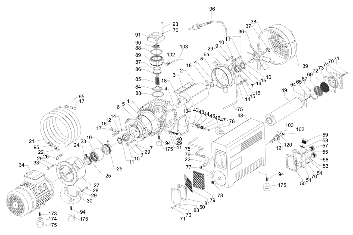
Exploded view
Exploded view legenda
- 1 Cylinder
- 2 Rotor
- 3 Rotor Vane
- 4 Sleeve
- 5 O-Ring
- 6 End-Plate
- 6a End-Plate
- 7 Tapper Pin
- 10 Sleeve Bearing
- 11 Shaft Seal
- 11a Hex Head Screw
- 11 B Hex Head Screw
- 12 Support Ring
- 13 Hex Head Screw
- 15 Screw
- 15a Hydraulic Fitting
- 15b Hydraulic Fitting
- 16 Oil Recir Culation Valve
- 17 Oiltubing
- 18 Key
- 19 Coupling
- 21 Cooling Coil
- 23 Coupling
- 24 Coupling
- 25 Machine Screw
- 26 Protest Cover
- 27 Flange
- 28 Fitting
- 29 Hydraulic Fitting
- 30 Bracket
- 31 Machine
- 32 Plug
- 34 Motor
- 36 Fan Opp. Motor Side
- 37 Retaining Ring
- 38 Fan Cover
- 40 Cylinder Separator Gasket
- 42 Exhaust Valve
- 43 Socket Set Screw
- 44 Exhaust Valve
- 45 Compressing Ring
- 46 Hex Head Screw
- 47 Cylinder Cover Screw
- 48 Exhaust Box
- 49 Hex Head Screw
- 49a Exhaust Filter
- 50 Gasket
- 51 Inlet Screen
- 53 O-Ring
- 56 Plug
- 57 Plug
- 58 O-Ring
- 59 Oil Separator
- 61 Hydraulic Fitting
- 63 Oil Return Line
- 64 Spring Plate
- 66 Exhaust Cover Gasket
- 67 Lock Washer
- 67a Retaining Ring
- 69 Screen
- 70 Lock Washer
- 72 Screen
- 73 Sheet Metall Baffle
- 74 Exhaust Cover Silencer
- 77 Hydraulic Fitting
- 77a Oil Tube
- 78 Socket Head Screw
- 79 Demister Steel
- 80 Oil Mist Filter
- 81 Lifting Eye Bolt
- 83 Cover Plate
- 84 Valve Plate
- 85 Compression Spring
- 86 Valve Plate
- 87 O-Ring
- 88 O-Ring
- 89 Inlet Flange Lower
- Housing
- 90 Inlet Screen
- 91 Inlet Flange
- 95 Hydraulic Fitting
- 96a Gas Ballast Pin
- 96b Air Mouth
- 96c Directional Valve
- 96d Oil Tube
- 104 Copper Bush
- 105 Double Head Screw
- 110 Hydraulic Fitting
- 118 Hex Head Screw
- 123 Hex Head Screw
- 148 Copper Washer
- 149 Washer
- 175 Rubber Foot


